Sensors Tab
The Sensors tab configures sensor hardware, accelerometer and magnetometer calibration, and provides live sensor data graphs. It consolidates sensor setup that was previously split across the Configuration and Setup tabs.
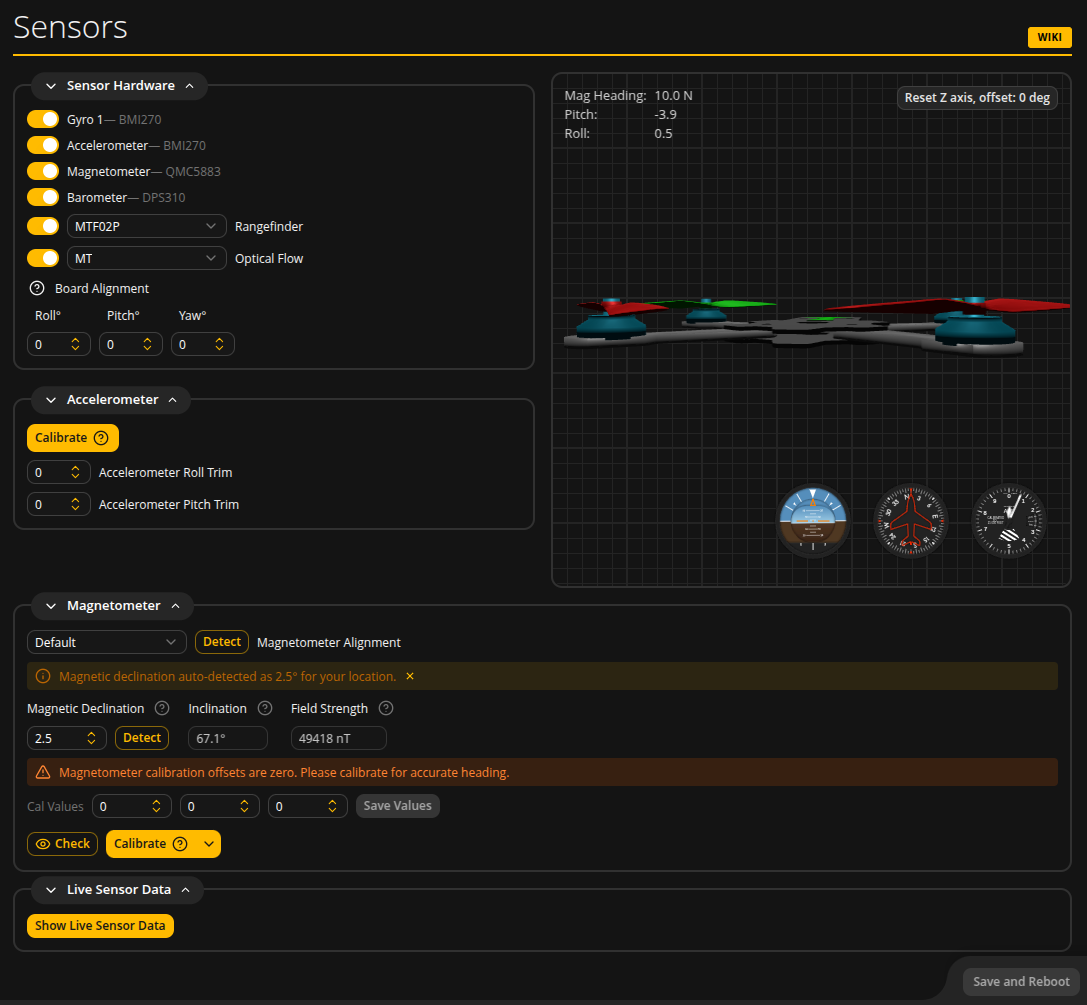
Sensor Hardware
The Sensor Hardware section shows detected sensors and lets you enable or disable them. When a sensor is detected, its hardware name is shown next to the toggle (e.g. "Gyro 1 -- BMI270", "Accelerometer -- BMI270", "Magnetometer -- QMC5883").
| Setting | Description |
|---|---|
| Gyro | Always enabled. Shows the detected gyro hardware. On boards with dual gyros, a "Gyro to use" selector lets you choose Gyro 1, Gyro 2, or Both. |
| Accelerometer | Enable or disable the accelerometer. Required for angle/horizon modes, GPS Rescue, and magnetometer heading correction. |
| Magnetometer | Enable or disable the magnetometer. When enabled, additional alignment and calibration options appear below. |
| Barometer | Enable or disable the barometer. Used for altitude estimation. |
| Rangefinder | Enable or disable a rangefinder sensor (e.g. MTF02P). Only visible when the firmware includes rangefinder support. |
| Optical Flow | Enable or disable an optical flow sensor. Only visible when the firmware includes optical flow support. |
Board Alignment
Compensates for a flight controller that is not mounted flat or square to the frame. Enter roll, pitch, and yaw correction angles in degrees (decidegrees in CLI). These corrections apply to the gyro, accelerometer, and any sensors that share the FC's coordinate frame.
Board Alignment Wizard
On firmware with API >= 1.48, a new Board Alignment Wizard is available to assist with setting the correct board orientation. It provides step-by-step guidance for interactively determining the correct roll, pitch, and yaw angles by analyzing accelerometer and gyroscope readings while the flight controller is tilted as instructed.
Sensor Alignment (Legacy)
On firmware with API < 1.47, separate alignment dropdowns for Gyro 1, Gyro 2, and Accelerometer appear here. On newer firmware, sensor alignment is handled automatically or via the Board Alignment fields.
Accelerometer
Calibrate
Click Calibrate to start accelerometer calibration. Place the quad on a flat, level surface and do not move it during calibration. The button shows "Calibrating..." while in progress. A warning banner appears if the accelerometer has not been calibrated yet.
Accelerometer Trim
Fine-tune the accelerometer reading with Roll and Pitch trim values. These small corrections compensate for minor mounting imperfections that remain after calibration.
Magnetometer
The Magnetometer section appears when a magnetometer is detected and enabled. It provides alignment configuration, magnetic reference detection, calibration offset editing, and calibration tools.
For comprehensive magnetometer setup instructions, see the Magnetometer guide.
Magnetometer Alignment
A dropdown to select the mounting orientation of the magnetometer relative to the frame. Options include Default, CW90, CW180, CW270, and their flipped variants for inverted mounting (common with GPS-integrated magnetometers). Selecting "Custom" reveals Roll, Pitch, and Yaw angle inputs for arbitrary orientation corrections.
The Detect button (API >= 1.47) automatically determines magnetometer alignment by analyzing sensor data while you slowly rotate the quad. It collects samples, detects the most likely orientation, and shows a confidence level. You can then apply or discard the result.
Magnetic Declination, Inclination, and Field Strength
These fields show the local magnetic reference values used for heading correction.
| Field | Description |
|---|---|
| Magnetic Declination | The angular difference between magnetic north and true north at your location. Editable -- enter your local value, or click Detect to auto-fetch it from online geomagnetic models based on your GPS or browser location. |
| Inclination | The angle at which the Earth's magnetic field dips into (or out of) the ground. Read-only, populated by the Detect function. |
| Field Strength | The total intensity of the local magnetic field in nanoteslas (nT). Read-only, populated by the Detect function. |
An informational banner shows when declination has been auto-detected. A warning banner appears if the declination value differs significantly from the detected value.
Cal Values
Three editable fields showing the current magnetometer calibration offsets (X, Y, Z). These values are subtracted from raw sensor readings to center the data around zero.
You can edit these values manually and click Save Values to write them to the flight controller via CLI. This is separate from the global "Save and Reboot" button because mag calibration values are stored via CLI commands, not the normal MSP parameter path.
Check Mode
Click the Check button (eye icon) to enter Check mode. This opens a 3D sphere visualization showing live magnetometer readings plotted as dots. Check mode uses the current calibration values and does not modify them. Use it to:
- Verify that the current calibration is accurate (dots should form a sphere centered on the origin)
- Confirm that the magnetometer orientation is correct
- Observe the effect of nearby magnetic interference
Calibration
Click Calibrate to start magnetometer calibration. A dropdown arrow next to the button offers different calibration modes:
| Mode | Description |
|---|---|
| Client Cal (Guided) | Recommended. The configurator guides you through 6 orientations (flat, inverted, nose up, nose down, left side up, right side up) with auto-advancing prompts every 10 seconds. A 60-second countdown timer is shown. The configurator computes calibration offsets using sphere fitting. Click Save Calibration to accept the result. |
| Client Cal (Free) | Rotate the quad freely in all directions. The configurator collects samples and computes offsets. No orientation prompts -- you decide when coverage is sufficient. |
| Firmware Cal (Legacy) | Triggers the firmware's built-in 30-second calibration. The firmware computes and auto-saves the offsets. Requires a physical tap/shake to initiate data collection within a 15-second window. |
During calibration, the 3D sphere view shows:
- White dots accumulating as you rotate the quad, forming a sphere
- Axis lines (red X, green Y, blue Z) in the quad's frame of reference, showing live field strength per axis
- A white nose-direction line from the quad to the current sample position
- An orange field reference arrow showing the local magnetic field inclination angle
- Compass labels (N, S, E, W) on the celestial sphere
- A green dot showing the current firmware calibration offset position
- A grey dot showing the computed sphere center (the new calibration offset)
- Quality score and coverage assessment
The quality indicator shows Good, Fair, or Poor based on the sphere fit residual and angular coverage uniformity. Aim for complete angular coverage with no visible gaps in the dot sphere.
During calibration you can:
- Cancel to discard all data and return to idle
- Clear to reset collected samples and start over without leaving calibration mode
- Save Calibration (Guided/Free modes) to write the computed offsets to the flight controller
Legacy Firmware (API < 1.47)
On older firmware without CLI-over-MSP support, only a single Calibrate button is shown. This triggers the firmware's built-in magnetometer calibration (equivalent to Firmware Cal Legacy mode).
Live Sensor Data
Click Show Live Sensor Data to display real-time graphs of sensor readings. The graphs auto-scale and show data from all enabled sensors. The available data channels depend on which sensors are active and the selected debug mode.
Debug values from the firmware are also shown here. Set the Debug Mode in the Blackbox/Logging tab to choose which internal values are exposed. For a reference of available debug modes, see the Debug Modes guide.
Save and Reboot
Click Save and Reboot at the bottom of the page to persist all sensor configuration changes (hardware enables, alignments, board alignment, accelerometer trim). Note that magnetometer calibration offsets are saved separately via the Save Values button in the Cal Values section.